Chapter 2: The Graphics Pipeline
Overview
The purpose of this chapter is discuss a way to draw shapes/geometry to 2D screen. The 2D screen is the monitor that is attached to your computer. The shapes and geometry are what we want to draw. We are going to focus on triangles in this part, though points and lines are other shapes that you could draw. Triangles are the main type of shape, or “primitive”, that is rasterized by most rasterization pipelines. Triangles are 3D shapes with some useful properties, and most other shapes can be created using multiple triangles.
The Graphics Pipeline is the process by which we convert a description of a 3D scene into a 2D image that can be viewed. This involves both transformations between spaces and conversions from one type of data to another.
Spaces
What is a space? Consider if you and I are standing in a room, 6 feet apart and facing the same direction. Exactly half way inbetween us is a table, and I am on the left of the table. If I were to answer “where is the table”, I would likely say the table is 3 feet to my right. But you would say the table is 3 feet to your left. Neither of us is wrong, we’re just describing relationships in space using a difference reference point. We might say that I am describing the position of the table in “my coordinates” while you are describing it in “your coordinates”.
In computer graphics, we sometimes call these two different coordinate systems spaces. A lot (seriously, a lot) of computer graphics has to do with transforming geometry between spaces. Usually, the spaces are different in more complicated ways (consider if you turned yourself 45 degrees, and I flipped over and did a headstand - our descriptions of the table’s position would now be more complicated and different).
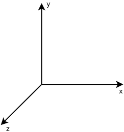
It’s nice to have a common frame of reference for these things. Usually, we describe the positions of most things in our scene in terms of “world coordinates”. This “world space” has a common reference point, or origin, from which the positions of all other objects are described. The world coordinate system also has a sense of directionality, e.g. which way is up, but we’ll discuss this later.
In our rasterizers, our task will be to take triangles with coordinates stored in world space, and transform them into pixels that we can color on the screen.
Types of Geometry
As discussed, the elements of our scenes will usually be primitive geometry, specifically either points, lines, or triangles. The geometry can be expressed in 2D coordinates, but usually we’ll be talking about 3D geometry.
The output of our rasterizer will be an image that can be viewed. This image will be a two-dimensional array of color values. These color values are called pixels, or “picture elements”.
We’ll usually talk about these pixels as a x and y coordinate on the screen. These coordinates will be integers, and will range from 0 to the width or height of the screen.
![]()
We will need to find a way to transform from world coordinates to these pixel coordinates, but we’ll cover that after we first introduce the main stages of the graphics pipeline.
The Graphics Pipeline
The Graphics Pipeline exists in a variety of forms depending on the type of computer graphics and rendering you are doing.
What we’ll introduce now is the rasterization pipeline used by OpenGL, which will be more or less what implement for our software rasterizer.
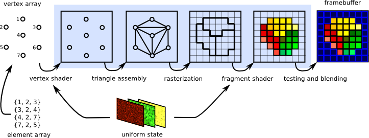
input specification: what are the vertices?
- the type of geometry we’ll be rendering is specified, in a form that is convenient for the rasterization process we’re using.
vertex shader: move to camera’s perspective
- world/object space → screen coordinates: we transform the coordinates of our input geometry from world space to a new space that is aligned with the camera’s persective.
rasterization: which pixels are inside triangle?
- Rasterization involves determining the pixels that a given primitive covers on the screen, so that we can compute the colors of each covered pixel.
fragment shader: what color is each pixel?
- For each given pixel that is covered by the primitive, compute the expected color. For starters we’ll likely just color each pixel a specific color, e.g. red. Later, the fragment shader may be used to perform more complicated per-pixel computations, such as a lighting calculation to determine whether a pixel is brightly lit or dim.
testing and blending: which pixels are visible?
- At this point we need to perform what’s called a depth test to determine whether a given pixel has already been computed for a closer object. For any given perspective, some geometry may be hidden by other geometry that’s in front of it. We’ll resolve this on a per-pixel basis, after the rasterization stage.
Software Rasterizer
Our implementation of a software rasterizer will have four major stages.
- Read in triangles
- We’ll have some way for the user of our software to specify what geometry should be rendered. Initially, you may want to use simple command-line arguments, though eventually we’ll want a way to import triangle meshes from files.
- Convert triangels to windows coordinates
- We need to transform the 3D coordinates of each triangle vertex from world space to window coordinates or pixel coordinates, so that they can be rasterized.
- Rasterize each triangle.
- Rasterization determines which pixels a given triangle covers in pixel space.
- We’ll use barycentric coordinates to test whether a given point is inside the triangle, and also to interpolate colors across the triangle (if different vertices have different colors)
- Write interpolated color values per pixel
- (using a z-buffer test to resolve depth comparisons)