Chapter 23: Clipping, Culling, and Hidden Surface Removal
Graphics Pipeline Review
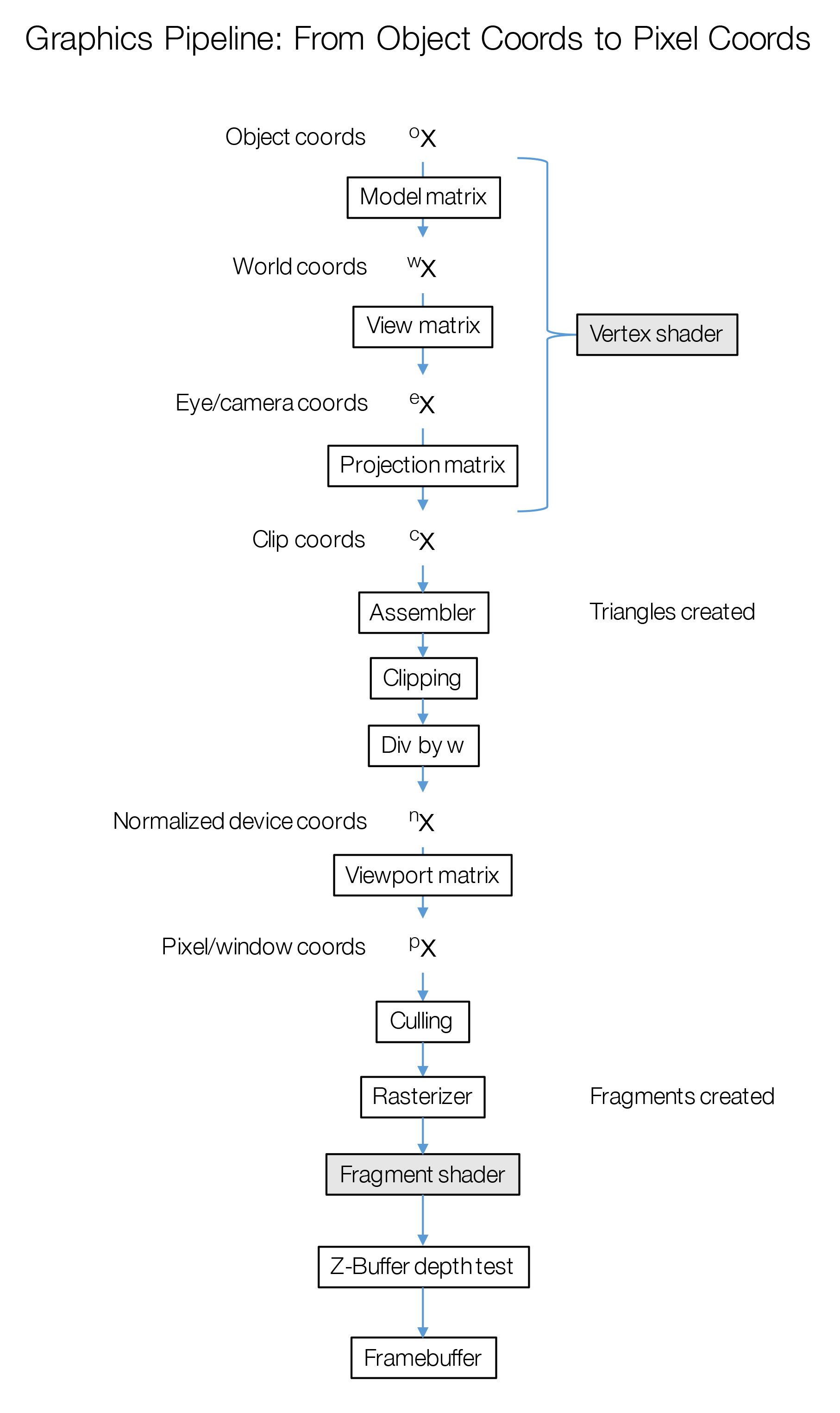
Object space: the coordinates stored in the mesh file, uploaded to the VBO, and sent to vertex shader as in vec3 vPosition
World space: M * vPosition
View space: V * M * vPosition
Clip space: P * V * M * vPosition
Normalized device coords: clip.xyz / clip.w
Window coords: gl_FragCoord
Clipping
Once vertices have been assembled into triangles, they are stored in clip coordinates. In normalized device coordinates, points are in the -1.0 to 1.0 range in X and Y if they will be visible. These coordinates will map to window/pixel coordinates in the 0, 0 to width, height range. But back in clip coordinates, that maps to -w and w.
The Z values of coordinates in NDC are from -1.0 to 1.0 and this will map to depth values. Similarly, Z values in clip coordinates will be in the range -w to w.
Clipping occurs to prevent the rasterization of any triangles that are outside of the view volume. If a triangle is outside of the view volume, there is no reason to attempt to rasterize it (it will generate no visible fragments).
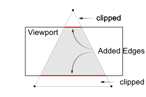
If a triangle is partially outside the view volume, it will be reconstructed such that no part is outside of the view volume. This may involve creating additional triangles.

Further information can be found here.
Culling
Culling refers to the process of removing objects from the graphics pipeline at some early stage, to avoid further computation on something which will inevitably not be visible. In this respect it is similar to clipping, but generally the term means any approach other than the standard clipping algorithm that is part of the graphics pipeline.
One form of culling is backface culling. This is useful when some watertight mesh will only be visible from the outside (as is often the case in many graphics applications). In this case, any face which is pointing away from the camera will not be visible. Such faces can be removed by checking the “winding order” of all triangles.
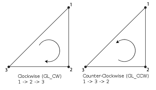
By default, OpenGL expects counter-clockwise winding order for triangles that are facing forwards. With backface culling enabled, triangles facing the other direction will be automatically culled. This occurs before rasterization.
Further information can be found here.
Other Culling Techniques
There are other techniques that can be used to cull objects at various stages in the pipeline. They will be covered more extensively in CSC 476.
-
View Frustum Culling: Determine visible objects on the CPU side by comparing bounding volumes against the view frustum. Objects that are guaranteed to not be visible are omitted from rendering altogether.
-
Occlusion Culling: Determine whether large objects close to the camera would occlude objects in the distance. If so, either omit those objects or remove them at some point in the pipeline.
Depth
There’s a couple of important things to note about the projection transform. It is constructed using a “near” and “far” value and . For mathematic reasons, we can’t use for the near value, or nothing will be visible. We’re also limited in general for our choices of these values. We can’t set near too close, or set far too distant, or else the precision of the depth buffer will be compromised.
An effect called z-fighting is produced when the near and far values are set in such a way that the precision of the depth buffer is unsufficient to represent fragment depths appropriately. Numerical imprecision issues prevents the depth test from working in a consistent or expected manner, and objects will appear to bleed through other objects in a shimmering/noisy manner.
A more in-depth (har har) explanation can be found here.
Projection Matrix Derivation
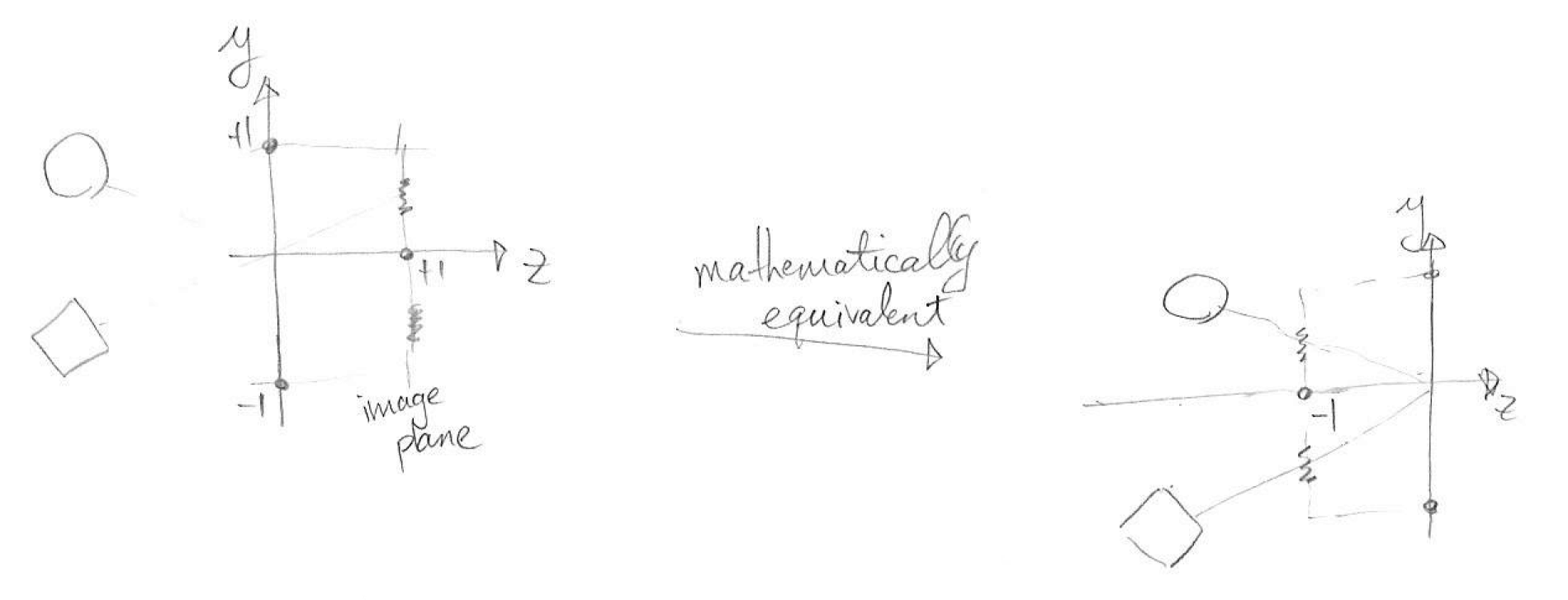
Assumption: pinhole camera, everything in eye/camera coords
With the image sensor on the plane: