Chapter 37: Spatial Data Structures
Introduction
When we add complexity to our scenes and recursive ray tracing, rendering can start to take a very long time…
In general, ray tracers get bogged down in the ray-object intersection loop, especially as the number of objects goes up or the number of rays goes up). A solution is to add spatial data structures which help answer the question: “where is this ray relative to the other objects in the scene?” - as it would be nice to avoid testing a ray against geometry that is not nearby.
The most commong spatial data structures are:
- Bounding Box Hierarchies
- Uniform Spatial Subdivision
- Binary Space Partitioning Tree
Ideally, with any spatial data structure, we’d like to eliminate as many objects from our search as possible.
We want a well-balanced tree that will reduce our search from n to log(n).
Of course, testing our ray against an additional data structure has cost, but this cost should be minimal compared to testing against all other objects.
We will cover implementation of a Bounding Volume/Box Hierarchy here, since it is probably the most straightforward to implement for our raytacer.
Bounding Volume Hierarchy
The general idea of a bounding volume hierarchy is to enclose all geometry in a series of nested volumes. We will use axis-aligned bounding boxes to produce a bounding box hierarchy.
We will need to compute bounding boxes for each object as well as groups of multiple objects.
An axis-aligned bounding box can be represented by a min and max vec3 position.
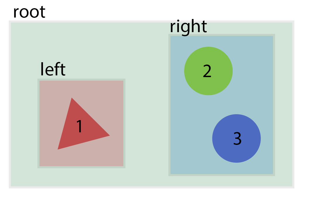
We want a tree of bounding boxes, with each node being a bounding box that contains the entirety of all child node boxes. The root node of the tree is a bounding box that contains the entire scene. The leaf nodes of the tree are the objects we want to render.
Example scene with bounding volumes:
Example bounding volume hierarchy:
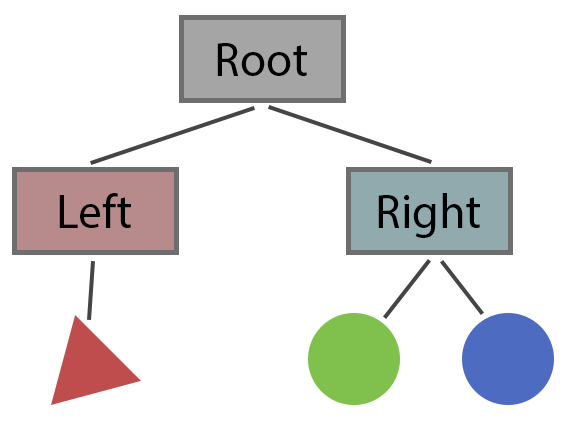
The general tree traversal for ray intersection looks like this:
if (ray hits root) then
    // test subtrees
    if (ray hits left) then
        // descend and check left tree
        check triangle/sphere for intersection

    if (ray hits right) then
        // descend and check right tree
        if (ray hits left) then
            check triangle/sphere for intersection
        if (ray hits right) then
            check triangle/sphere for intersection

    if (any hits on subtrees) then
        return closest of hits
        // likewise if just one
    else
        return false // no hits
Note the recursive nature of this traversal. In your actual implementation, you will likely want some sort of BoundingVolumeNode class with a list of children (or just left/right pointers) and a recursive intersect method.
It’s important to note that finding an intersect on the left side of a node doesn’t mean we can skip the right side. There could be intersects on both left and right subtrees - we need to return the closest of the two.
Bounding Boxes
First we need to compute bounding boxes for each type of object in our scene.
I recommend creating an axis-aligned bounding-box class with a few methods:
class AABB
{
    vec3 min, max;

public:
    void Reset(vec3 pt) {
        min = max = pt;
    }

    void AddPoint(vec3 pt) {
        min.x = glm::min(min.x, pt.x);
        min.y = glm::min(min.y, pt.y);
        min.z = glm::min(min.z, pt.z);
        max.x = glm::max(max.x, pt.x);
        max.y = glm::max(max.y, pt.y);
        max.z = glm::max(max.z, pt.z);
    }

    void AddBox(AABB other) {
        AddPoint(other.min);
        AddPoint(other.max);
    }
};
Then, we can create a bounding box for each of our shapes like so:
// Sphere
box.Reset(center - vec3(radius));
box.AddPoint(center + vec3(radius));
// Triangle
box.Reset(v1);
box.AddPoint(v2);
box.AddPoint(v3);
For boxes, the bounding box is the same as the object. I recommend keeping planes out of your bounding-volume hierachy. For planes, the bounding box will stretch from to in at least two axis. Keeping these in the hierarchy would reduce its effectiveness significantly, and in general our scenes tend to contain few planes. A scene with a thousand triangles or spheres is interesting, a scene with a thousand planes is not.
To compute the composite box of two shapes, just add one to the other.
To handle bounding boxes of transformed shapes, compute the bounding box in object space and transform it into world space. To transform a bounding box, this algorithm will create an admissable box:
vector<vec3> verts = box.compute_8_vertices();

for (vec3 & v : verts) {
    v = m * v; // have to promote to vec4, you know the drill
}

box.Reset(v[0]);
for (int i = 1; i < 8; ++ i)
    box.AddPoint(v[i]);
It is not sufficient to simply transform the min and max corners.
Consider the result of a long and narrow shape is rotated 45 degrees.
The containing AABB will need to be significantly larger in volume.
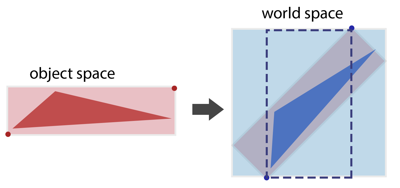
It is clear that the box formed by the transformed min and max (dotted outline) does not cover the transformed shape. The box formed by transforming each corner of the box is also a little larger than it needs to be. However, finding a true-fitting box for a transformed shape would be difficult for all general shapes (though in the case of some like triangles it would be quite easy), and for the purposes of our hierarchy it is not a huge problem if boxes are slightly larger than they should be, though it would be a huge problem if boxes didn’t fully cover the shapes they are supposed to contain.
Building the Tree
So the big question becomes how to build a tree such that it is well balanced (e.g. a depth closer to log(n) than to n).
There are many options to do this.
Shirley suggests building a strictly binary tree with only two children per level, where the bounding boxes are guaranteed to bound everything contained in their subtrees
but not guaranteed to enclose all objects that may overlap it spatially.
Ideally we would like to build a tree that has minimal spatial overlaps, but there are many different ways to build the tree.
One method (proposed by Shirley, he proposes two different methods) is to loop over the dimensions, cutting the objects into two groups. The heuristic to accomplish this rough partitioning is to sort the geometric objects along a given axis (sort them based on their centers) and then divide them into two sublists.
First we cut in X, then in Y, then Z before going back to X.
class bvh_node {
    constructor() {
        this.left = null;
        this.right = null;
        this.objs = null;
    }
}

function recursive_tree_build(objs, axis /* 0=x, 1=y, 2=z */) {
    if (objs.length() <= 1) {
        this.objs = objs;
        this.calculateBBox();
        return;
    }

    sort_objects_on_axis(objs, axis);

    this.left = new bvh_node();
    this.right = new bvh_node();

    this.left.recursive_tree_build(left_half_arr(objs), (axis + 1) % 3);
    this.right.recursive_tree_build(right_half_arr(objs), (axis + 1) % 3);

    this.calculateBBox();
}
The tree created by this method could be optimized by not just blindly rotating through the axis but carefully picking the axes to split on (e.g. such that the sum of the volums of the bbox of subtrees is minimized) or we could rewrite such that they contain roughly the same amount of physical space (not just dividing based on the # of elements). However, the above method works well for scenes with objects of similar size that are “evenly” distributed.